

 Chinese
- HOME >> NEWS >> Industry news
NEWS
Latest Product


Contact Us
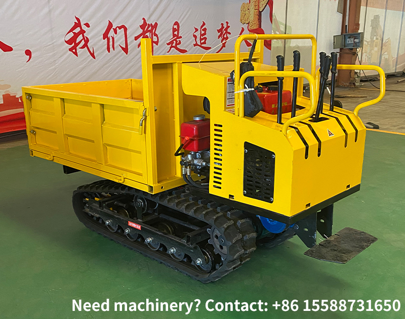
How to Adjust the Track Tension of Tracked Transporters and What Problems Will Be Caused by Improper Adjustment?
2026-01-10The core of adjusting the track tension of a tracked transporter is to adjust the position of the idler wheel, and achieve precise control of track tightness by changing the distance between the idler wheel and the driving wheel. The specific operations and the impacts of improper adjustment are as follows:
I. Methods for Adjusting Track Tension
Track tensioning mechanisms are mainly divided into two types: screw adjustment type and hydraulic adjustment type, which are suitable for tracked transporters of different tonnages:
Screw Adjustment Type (mostly used for small-sized tracked transporters)
Operation Steps
First, park the transporter on a flat surface and loosen the fixing bolts of the idler wheel bearing housing.
Locate the tensioning screw on the side of the track (usually equipped with an adjusting nut and a lock nut). Rotate the nut clockwise, the idler wheel will move outward and the track will be tensioned; rotate the nut counterclockwise, the idler wheel will move inward and the track will be loosened.
During adjustment, adjust the tracks on both sides synchronously to avoid track deviation caused by uneven tightness on one side.
Standard tension judgment: Press the track vertically by hand at the middle section (between the top roller and the supporting roller) — the sag amount should be controlled within 20–50 mm (take the smaller value for small-sized vehicles and the larger value for medium-sized vehicles).
After adjustment, tighten the fixing bolts of the bearing housing and the lock nut of the tensioning screw to prevent loosening.
Hydraulic Adjustment Type (mostly used for medium and heavy-duty tracked transporters)
Operation Steps
Start the hydraulic system of the transporter and locate the control valve of the tensioning cylinder (some models are equipped with a manual pump).
Operate the valve to inject oil into the tensioning cylinder; the cylinder will push the idler wheel to move outward and the track will be tensioned. Open the oil drain valve, the cylinder will release pressure, and the idler wheel will move inward under the pulling force of the track, thus loosening the track.
The tension judgment standard is the same as that of the screw adjustment type. After adjustment, close the hydraulic valve and lock the position of the cylinder.
Regularly check the sealing performance of the tensioning cylinder to prevent gradual track slack caused by oil leakage.
II. Hazards of Improper Track Tension Adjustment
Problems Caused by Over-tight Tracks
Accelerated component wear: Over-tight tracks will continuously exert excessive pressure on the driving wheel, idler wheel, supporting roller and top roller, leading to rapid heating and wear of the wheel train bearings, and even tooth chipping.
Increased power loss: Excessive track tension will increase the friction resistance during driving, which increases engine load and fuel consumption, while raising the failure rate of the transmission system.
Fatigue fracture of tracks: Long-term over-tightening will accelerate the metal fatigue of track shoes and track pins, which is prone to track pin fracture and track shoe cracking.
Problems Caused by Over-loose Tracks
Track deviation and detachment: Loose tracks cannot maintain straight-line driving, and are prone to unilateral deviation; in severe cases, the tracks will directly fall off the wheel train, resulting in machine shutdown.
Impact damage to tracks: During driving, loose tracks will shake up and down, causing severe impact with the idler wheel and supporting roller, leading to track shoe deformation and weld cracking of the wheel train.
Degraded steering performance: When turning, over-loose tracks cannot effectively engage with the driving wheel, resulting in increased steering resistance and even steering failure, which is especially risky during heavy-load transportation and climbing.
Supplementary: Suggestions for Fine-tuning Tension under Different Working Conditions
Mud and swamp conditions: The track can be slightly loose (the sag amount is close to the upper limit), so as to avoid excessive resistance caused by soil accumulation between the track and the wheel train.
Mining and gravel conditions: The track should be moderately tight (the sag amount is close to the lower limit) to prevent track damage caused by gravel jamming.