

 Chinese
- HOME >> NEWS >> Company news
NEWS
Latest Product


Contact Us
Core Components and Working Principle of the Crawler Travel System for Crawler Excavators
2026-01-29The crawler travel system is the core walking mechanism of a crawler excavator, undertaking the tasks of supporting and moving the entire self-weight of the machine body and operational loads. Its core design is built around low ground contact pressure, strong ground adhesion, and high walking stability. The whole system features a bilateral independent drive structure (the left and right crawlers can be controlled separately to realize steering and in-situ slewing). Its core components are divided into two major parts: mechanical execution components and power control components. The working principle is a closed-loop transmission of "hydraulic power transmission - mechanical component linkage - crawler meshing with the ground for walking". The detailed breakdown is as follows:
I. Core Components of the Crawler Travel System (Mechanical Execution + Power Control, Bilaterally Symmetric Layout)
The left and right crawlers of a crawler excavator each form an independent travel unit, and the two units share a hydraulic power source. The core components have no redundancy and clear division of labor. The mechanical execution components serve as the "actuators" for walking, and the power control components act as the "core of power and control" for walking. The specific components and their functions are as follows:
(I) Mechanical Execution Components (Direct Ground Contact/Mechanical Transmission, Concentrated Area of Core Consumable Parts)
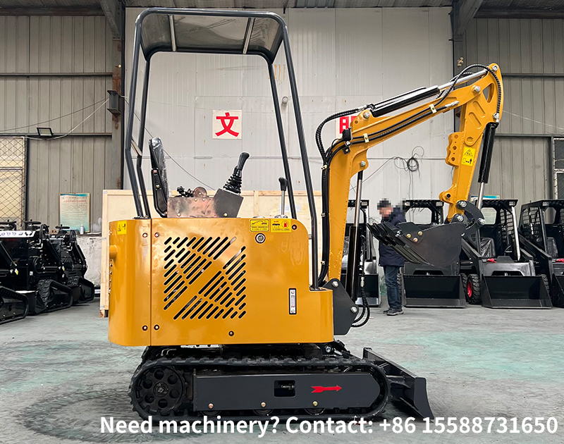
Crawler assembly: The core actuator of the travel system, an annular chain belt hinged by track shoes, track links, pin shafts and pin bushings. The track shoes are in direct contact with the ground, and the track links are connected into a chain ring through pin shafts/pin bushings to achieve meshing transmission with the drive sprocket. Wide, reinforced and anti-skid track shoes can be replaced according to operational scenarios to adapt to different terrains.
Drive sprocket: Mounted on the rear side of the crawler assembly (on the front side for a few models), it meshes precisely with the track links, receives power from the travel motor and transmits it to the crawler assembly to drive the crawler to rotate. Made of high-strength wear-resistant steel with meshing teeth on the surface, it is a "key meshing part" for power transmission.
Idler: Mounted on the front side of the crawler assembly and connected to the tensioning device, it guides the travel direction of the crawler, corrects crawler deviation, and adjusts the tightness of the crawler in cooperation with the tensioning device to prevent crawler derailment.
Support rollers: Evenly arranged between the excavator chassis and the crawlers, they directly support the entire self-weight and operational loads of the excavator. The quantity depends on the excavator tonnage (4-6 units per side for small excavators, 8-12 units per side for large excavators). They roll closely against the inner track links of the crawlers to reduce frictional resistance during crawler travel and prevent the crawlers from sinking due to excessive loads.
Carrier rollers: Mounted on the upper side of the crawler assembly, they support the upper part of the crawlers to prevent the crawlers from sagging and shaking under their own weight, ensure the straightness of the crawlers during travel, and reduce collision and wear between track links and other components. There are generally 2-3 units per side for small excavators, which can be increased to 4-5 units per side for large excavators.
Tensioning device: Mounted behind the idler and composed of a tension cylinder, a spring and a tension rod, its core function is to adjust the crawler tightness. By injecting or draining oil into the tension cylinder, it pushes the idler to move forward and backward, thereby tightening or loosening the crawler. The spring plays a buffering role to avoid excessive stress and damage to the crawler caused by ground bumps and impacts.
Track frame: A rigid steel structure frame, one on each side, serving as the mounting base for all mechanical execution components. It integrates components such as the drive sprocket, idler, support rollers and carrier rollers into a whole, and is connected to the excavator chassis frame to undertake load transmission. It adopts a thickened and reinforced design to ensure structural strength.
(II) Power Control Components (Power Transmission + Travel State Control, Core of Hydraulic Drive)
Travel motor: A hydraulic motor (mostly a piston motor) mounted inside the drive sprocket, acting as the "power source actuator" of the travel system. It receives high-pressure hydraulic oil from the hydraulic pump, converts hydraulic energy into mechanical energy, drives the drive sprocket to rotate, and provides power for crawler travel. It can realize stepless speed regulation to adapt to different travel speeds.
Travel reduction gearbox: Connected coaxially with the travel motor and the drive sprocket, its core function is to reduce speed and increase torque. The travel motor outputs high speed and low torque; after being decelerated by the gear set of the reduction gearbox, the output torque is increased to meet the travel power demand of the excavator under heavy load and complex terrain, and the rotation speed of the drive sprocket is reduced to ensure walking stability.
Hydraulic pump and hydraulic oil circuit: The hydraulic pump is driven by the excavator engine to supply high-pressure hydraulic oil to the travel motor. The hydraulic oil circuit includes a main travel valve, a travel control valve, oil pipes, filters, etc. The travel control valve (travel control lever in the cab) controls the flow direction, flow rate and pressure of hydraulic oil, thereby realizing the forward, backward, steering and travel speed adjustment (low/high speed) of the excavator.
Travel braking device: Including mechanical braking and hydraulic braking. Mechanical braking is parking braking (to prevent the excavator from rolling on slopes), and hydraulic braking is service braking (to realize travel deceleration/stop in cooperation with the control lever). Its core function is to ensure the braking reliability of the excavator during walking and parking, and is especially suitable for walking safety on slopes and muddy terrain.
II. Core Working Principle of the Crawler Travel System
The travel system of a crawler excavator adopts a bilateral independent transmission mode of hydraulic drive + mechanical meshing, with the engine as the total power source. The overall working principle can be divided into four core steps: power generation, power transmission, crawler travel and steering control. The left and right crawlers are controlled independently to realize all walking actions such as forward, backward, single-side steering and in-situ slewing. The specific process is as follows:
Step 1: Power Generation – The engine drives the hydraulic pump to output high-pressure hydraulic oil
After the excavator engine is started, it drives the main hydraulic pump and the special travel hydraulic pump (integrated hydraulic pump for some models) to rotate, converts mechanical energy into hydraulic energy, and outputs high-pressure and large-flow hydraulic oil. After being filtered by the filter, the hydraulic oil is delivered to the main travel valve through the hydraulic oil circuit to wait for operation instructions.
Step 2: Power Transmission – Hydraulic oil drives the travel motor, and the reduction gearbox increases torque and transmits it to the drive sprocket
The driver operates the travel control valve in the cab (the left/right control levers correspond to the left/right crawlers) to control the flow direction (forward/backward), flow rate (travel speed) and pressure (travel power) of hydraulic oil. High-pressure hydraulic oil enters the corresponding travel motor, pushes the plunger inside the motor to move, converts hydraulic energy back into mechanical energy, and drives the travel motor to rotate. The output shaft of the travel motor is connected to the travel reduction gearbox; after the speed is reduced and torque is increased by the planetary gear set/cylindrical gear set inside the reduction gearbox, the high-torque and low-speed power is transmitted to the drive sprocket, completing the conversion of power from the hydraulic system to the mechanical system.
Step 3: Crawler Travel – The drive sprocket meshes with the crawler, and the machine body moves through ground reaction force
The meshing teeth on the surface of the drive sprocket mesh precisely with the track links of the crawler assembly. When the drive sprocket rotates, it drives the crawler assembly to perform an annular circular motion: the lower side of the crawler is in contact with the ground, the upper side is supported by the carrier rollers, and the support rollers support the machine body and roll with the crawler. When the crawler is in contact with the ground, due to the static friction (adhesion) between the anti-skid patterns of the track shoes and the ground, the crawler pushes the ground downward and backward. According to Newton's Third Law, the ground exerts an equal and opposite forward reaction force on the crawler. This reaction force is transmitted to the excavator body through the crawler, support rollers and track frame, pushing the body to move forward/backward to realize walking.Core Principle: The crawler itself has no independent movement capacity; the movement of the machine body relies on the ground reaction force on the crawler, rather than the crawler directly "dragging" the machine body. This is also the key reason why crawler excavators are not prone to slipping on muddy and soft ground (the crawler has a large ground contact area and strong adhesion).
Step 4: Steering Control – Differential speed/single movement of the bilateral crawlers to realize steering through ground reaction force
A crawler excavator has no steering wheels, and steering is realized by the speed difference/single movement of the left and right crawlers. The hydraulic oil supply to the left and right crawlers is controlled by operating the travel control valve to realize different steering actions, which corely utilizes the "ground reaction force difference of the two crawlers to form a slewing torque of the machine body". The common steering methods and their principles are as follows:
Single-side steering (slow turn): One crawler travels normally while the other stops. For example, when the left crawler travels and the right crawler brakes, the static friction between the right crawler and the ground forms a slewing resistance torque, and the ground reaction force of the left crawler pushes the machine body to make an arc slewing around the right crawler to realize slow steering, suitable for conventional steering on flat terrain.
Differential steering (fast turn): The left and right crawlers travel at different speeds (e.g., the left crawler at high speed and the right crawler at low speed). The ground reaction force of the two crawlers forms a speed difference, and the machine body makes a small-radius arc slewing around the chassis center with a fast steering speed, suitable for position adjustment in narrow spaces.
In-situ slewing (zero-radius steering): The left and right crawlers travel at the same speed and in opposite directions (e.g., the left crawler moves forward and the right crawler moves backward). The ground reaction forces of the two crawlers are equal in magnitude and opposite in direction, forming a slewing torque around the chassis center of the machine body to realize 360° in-situ slewing. Suitable for operational positioning in extremely narrow spaces, it is one of the core advantages of crawler excavators.
III. Supplementary: Core Design Features of the Travel System (Adapting to Excavator Operational Requirements)
Bilateral independent drive: The left and right crawlers have no mechanical connection and are completely controlled independently by the hydraulic system, which can realize arbitrary steering actions and adapt to the operational requirements of narrow spaces in engineering construction.
Low ground contact pressure: By increasing the crawler ground contact area (wide track shoes) and arranging support rollers evenly, the self-weight of the machine body is dispersed on a larger ground contact surface to reduce the ground contact pressure per unit area, adapting to low-bearing-capacity terrains such as mud, soft ground and sand.
Stepless speed regulation + high torque: Hydraulic drive realizes stepless adjustment of travel speed (low speed for heavy load / high speed for transshipment), and the torque-increasing effect of the reduction gearbox ensures the travel power of the excavator on slopes and heavy load terrain. Conventional crawler excavators can climb slopes with an inclination of 30° to 45°.
Self-buffering and anti-derailment: The spring of the tensioning device can buffer the impact of ground bumps on the crawler; the idler corrects the crawler travel direction in cooperation with the tensioning device; the support rollers and carrier rollers limit the vertical shaking of the crawler, which greatly reduces the risk of crawler derailment.